
A Smart Crimping Tool brings measurement, control, and traceability to a task once judged mainly by hand pressure. It combines a crimping mechanism with force sensors, position detection, and a digital controller. During operation, the tool monitors force and stroke in real time. It then compares the result with programmed limits. A green signal can confirm an acceptable crimp. An error alert can stop production before a weak connection enters a vehicle, machine, or control cabinet.
This technology reflects a wider manufacturing shift. Deloitte’s 2024 Smart Manufacturing and Operations Survey reported that 86% of surveyed manufacturing leaders expected smart manufacturing to become a major competitiveness factor within three years. The trend is also supported by the industrial automation market. MarketsandMarkets projects strong growth in connected automation systems through 2029, driven by sensors, data platforms, and quality monitoring. These figures do not measure Smart Crimping Tool sales directly. However, they show why connected hand tools are gaining attention on modern production lines.
In practical use, an operator selects the terminal type, wire size, and approved crimp profile. The tool records force curves, cycle counts, and sometimes operator identification through software. Bluetooth or USB connectivity can send this data to a quality database. IPC/WHMA-A-620 remains an important reference for cable and wire harness workmanship. A connected tool does not replace trained judgment or calibration. It can still misread a damaged terminal. It can still be used incorrectly. That uncomfortable limitation matters. Reliable crimping depends on the tool, the terminal, the conductor, and disciplined inspection.
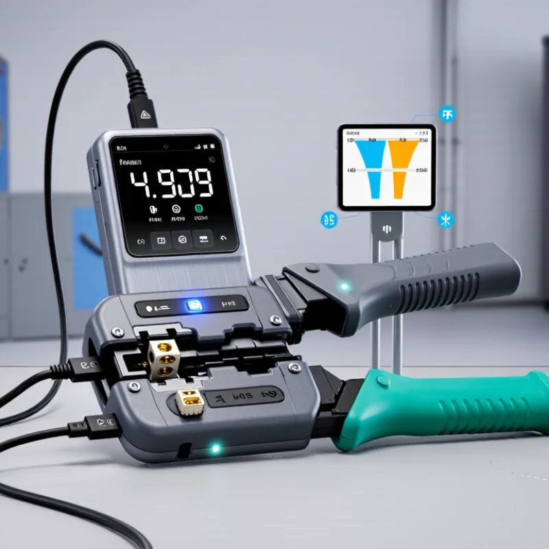
Smart Crimping Tools Defined: Digital Control Beyond Conventional Hand Crimpers
What Is a Smart Crimping Tool and How Does It Work?
Smart crimping tools add digital control to a traditionally mechanical task. Conventional hand crimpers depend mainly on operator strength and visual inspection. A smart model measures force, stroke, cycle count, and sometimes jaw position. Its internal sensor compares each crimp with programmed limits. The tool can then show a pass, warning, or failure signal.
This matters because small variations can create hidden connection problems. The IPC/WHMA-A-620 standard emphasizes measurable requirements for wire and terminal assemblies. Meanwhile, the 2024 Global Workforce Study by the International Federation of Robotics reports continued pressure to improve industrial productivity and process consistency. A digital crimping tool supports that goal through stored force curves, calibration reminders, and traceable production records. It can connect with a crimping tool kit and help technicians verify repeatability across different shifts.
Tips:
Set the correct terminal, wire size, and crimp profile before pressing. Clean the jaws regularly. Check calibration at the interval recommended by the tool maker. Do not trust a green screen alone; inspect conductor position, insulation support, and pull-test results. Data can be wrong when the setup is wrong. That is the uncomfortable part. Digital control reduces guesswork, but it does not replace skilled judgment. In practice, users may also find that software updates, battery limits, or poor connectivity interrupt a smooth workflow. A smart tool is helpful, not magical.
Core Components: Dies, Sensors, Microcontrollers, Batteries, and Connectivity
A smart crimping tool combines mechanical pressure with digital measurement.
Its dies shape the terminal around the wire. Correct die geometry matters because loose crimps can increase resistance, while excessive force may damage strands. Replaceable dies also allow one tool to handle different terminal sizes.
Sensors measure force, position, or closing distance during each crimp.
A microcontroller reads these signals and compares them with programmed limits. It can detect an incomplete cycle, incorrect pressure, or a terminal placed poorly. The feedback may appear on a small display or through an indicator light. In practical work, this helps technicians check connections without relying only on visual judgment.
A rechargeable battery powers the motor, sensors, and control circuit.
Battery condition can affect performance, especially during repeated crimps. Connectivity adds another layer. Bluetooth or wired links may transfer cycle records, tool status, and maintenance data. Useful, but not flawless. A weak connection can interrupt records. A sensor can drift over time. Dust, vibration, and temperature can also change readings. Regular inspection and calibration remain necessary, even when the tool reports a successful crimp. The operator still needs to confirm the wire size, terminal fit, and die condition. Digital guidance improves consistency, but it does not replace careful workmanship.
How Crimp-Force Monitoring Detects Incomplete or Irregular Connections
A smart crimping tool combines controlled compression with real-time measurement. During each cycle, a force sensor records the pressure curve as the terminal closes around the conductor. The system compares that curve with a validated reference window. A missing wire, incorrect terminal, damaged strand, or incomplete compression can shift the curve. The operator sees an immediate pass or fail signal.
The method supports requirements described in IPC/WHMA-A-620E and IEC 60352-2, which emphasize crimp height, conductor position, insulation support, tensile strength, and electrical continuity. Traditional inspection may check only samples. A connected crimping tool can record every cycle, including force, stroke, time, tool ID, and work order. That matters when a line produces thousands of connections daily. A single abnormal peak may reveal folded strands. A low, short curve can suggest missing material or poor terminal engagement.
However, force monitoring is not magic. A correct-looking curve can still hide damaged plating or an unsuitable terminal. Calibration drift also creates false alarms. Technicians should combine force signatures with periodic pull tests and cross-section analysis. NASA workmanship guidance and automotive quality practices both stress documented verification rather than visual confidence alone. My practical concern is simple: many teams trust the green light too quickly. The crimping tool should support judgment, not replace it.
The Crimping Workflow: From Wire Preparation to Automated Quality Verification
A smart wire crimping tool connects preparation, controlled compression, and quality verification in one workflow. The operator first measures the conductor, strips insulation, and checks for damaged strands. Correct strip length matters. Exposed copper should match the terminal barrel, not extend beyond it. The tool then identifies the terminal and applies programmed force. A position sensor records the crimp height and compression profile during each cycle.
The 2024 Smart Manufacturing and Operations Survey, covering 816 manufacturers, reported that 86% viewed smart manufacturing as important to competitiveness. That pressure is visible on the production floor. A smart crimping tool can log operator ID, wire type, force, time, and result. It may reject a loose crimp before the harness reaches final inspection. The World Robotics 2024 report recorded 541,302 industrial robot installations in 2023, showing how automated inspection is becoming normal in high-volume work.
Quality verification should compare measurements with the IPC/WHMA-A-620 workmanship requirements. However, automation is not magic. A sensor can approve a crimp while insulation remains trapped inside the barrel. A technician still needs to inspect sample cuts, pull-test results, and terminal alignment. In practical line reviews, the smallest warning is often useful: unusual force, uneven bellmouth, or copper brushing the insulation. Data exposes patterns, but experienced hands still question the data. That gap deserves attention.
IEC 60352-2 Compliance and the Role of Industry-Specified Crimp Profiles
What Is a Smart Crimping Tool and How Does It Work?
A smart crimping tool combines controlled pressure with electronic monitoring. During each cycle, sensors record force, stroke, and completion status. The system can identify under-crimping, over-crimping, or an incomplete wire position. Some tools also store production data for later inspection. Useful, but not magical.
IEC 60352-2 provides requirements, test methods, and practical guidance for solderless crimped connections. Compliance depends on the complete connection system, not the tool alone. The terminal, conductor size, plating, insulation, and approved crimp profile must work together.
An industry-specified profile controls how the terminal barrel compresses around the conductor. It also supports stable electrical contact and mechanical strength. A correct-looking crimp can still fail a pull test or cross-section review. The die may be correct, but the wire may be wrong. That detail is easy to miss.
Tips:
Select dies for the exact terminal and wire range. Check calibration at defined intervals. Inspect sample crimps under magnification. Use pull-force testing when the application requires it. Review the force curve, but do not trust it blindly. Temperature, material variation, and worn tooling can affect results. Keep records for traceability. A short training note beside the workstation can prevent repeated errors.
Digital Traceability: Recording Force Curves, Tool IDs, Operators, and Timestamps
A smart crimping tool combines controlled compression with digital traceability. During each cycle, sensors record the applied force, stroke, duration, and release point. The system links this force curve to a unique tool ID, operator ID, work order, and timestamp. Engineers can then review the exact crimp, not just a pass or fail result.
This matters when a terminal looks perfect but performs poorly later. IPC/WHMA-A-620 emphasizes documented workmanship and measurable acceptance criteria for cable and wire assemblies. A 2023 global smart-manufacturing survey reported that 86% of manufacturers considered connected production important for future competitiveness. Traceable crimp data supports that goal. It can reveal worn dies, inconsistent hand pressure, or training gaps before defects multiply. Still, digital records are not magic. A badly calibrated sensor can create confident but false evidence.
Tips: Store force curves with the assembly serial number. Restrict edits and record every change. Compare new curves with approved reference curves, not only force limits. A wire crimping tool kit should also include calibration checks and verified dies.
Operators need practical feedback. A small screen can show “force low” or “cycle incomplete” immediately. A connected database can flag repeated failures by tool or shift. Timestamps also help investigators rebuild an event without relying on memory. Data can be incomplete. Cables may be reworked, and people may forget to scan them. That weakness deserves regular audits.
Applications Across Automotive, Aerospace, and Industrial Wiring Assemblies
A smart crimping tool combines controlled pressure, sensors, and digital records. It measures crimp force, die position, and cycle completion. Some systems also detect terminal misalignment before release. This turns a hidden connection into measurable production data. IPC/WHMA-A-620 remains a widely used workmanship reference for cable and wire harness assemblies. However, a pass reading cannot replace correct terminal selection or visual inspection.
Automotive wiring now faces greater complexity.
The International Energy Agency reported nearly 14 million electric cars sold worldwide in 2023. High-voltage circuits demand repeatable crimps, clear traceability, and careful insulation control. In a production cell, the tool can store force curves for each connection. Operators then identify weak crimps before vibration, heat, or moisture causes failure. The process feels simple, but small setup errors still matter.
Aerospace assemblies require disciplined documentation and extremely stable workmanship.
Commercial aviation outlook reports published in 2024 forecast more than 40,000 new aircraft over the next two decades. That growth increases demand for dependable harness production and maintenance. In industrial wiring, the International Federation of Robotics recorded 541,302 new industrial robot installations in 2023. Smart crimping helps connect sensors, motors, and control cabinets consistently. Yet automation is not perfect. Worn dies, incorrect wire stripping, or poor training can still defeat the system. Experienced technicians must review the data and the physical joint.
FAQS
What is a smart crimping tool?
It combines mechanical pressure with electronic monitoring. Sensors track force, position, and closing distance. The tool then checks each crimp against programmed limits.
Why do die shapes matter?
Dies form the terminal around the wire. The correct geometry supports electrical contact and mechanical strength. Loose crimps can increase resistance. Excessive force may damage wire strands.
Can one tool handle different terminal sizes?
Replaceable dies can support several terminal sizes. Each die must match the terminal and wire range. A convenient setup can still be wrong if the die is unsuitable.
What can the sensors detect?
Sensors may identify incomplete cycles, low pressure, excessive pressure, or poor wire placement. Results can appear through a display or indicator light. Useful, but not magical.
Does electronic feedback prove that a crimp is correct?
No. The operator should still confirm wire size, terminal fit, and die condition. Inspect sample crimps under magnification when possible. The reading may look perfect, yet the connection can fail testing.
What does IEC 60352-2 require for crimped connections?
It provides requirements, test methods, and guidance for solderless crimped connections. Compliance involves the complete system. Terminal, conductor, plating, insulation, and crimp profile must work together.
Why are pull-force tests and inspections important?
A correct-looking crimp may fail a pull test or cross-section review. Pull-force testing checks mechanical strength. Magnified inspection can reveal uneven compression or damaged strands.
How do batteries and connectivity affect tool performance?
Battery condition can influence repeated crimp cycles. Wireless or wired links may transfer records and maintenance data. Weak connections can interrupt records. Keep inspection routines anyway.
How often should a smart crimping tool be checked?
Check calibration at defined intervals. Inspect dies for wear, dust, and damage. Review force curves, but do not trust them blindly. Temperature and vibration can change readings.
Conclusion
A Smart Crimping Tool is an advanced version of the conventional hand crimper, combining precision mechanics with digital control and quality monitoring. Its core components typically include interchangeable dies, force sensors, a microcontroller, a rechargeable battery, and optional connectivity features. During operation, the tool measures the crimp-force curve and compares it with an industry-specified crimp profile. This helps identify incomplete, irregular, or inconsistent connections that may not be visible during a basic visual inspection.
The crimping workflow begins with wire preparation, terminal positioning, and die selection, followed by controlled compression and automated quality verification. Tools designed for suitable applications may support requirements related to IEC 60352-2 and internal assembly standards. They can also record force curves, tool identification, operator information, and timestamps, creating a digital traceability record for production review. These capabilities make Smart Crimping Tool systems valuable in automotive, aerospace, and industrial wiring assemblies where reliable connections, repeatable processes, and documented quality control are essential.